
This is a guide in progress and is no where near complete, but did want to get some initial information and links to the project files up while I work on the rest of the guide.
Have been working on a few project involving the nRF9160 lately and am trying to get support added into TinyGSM for the nRF9160, there is a discussion over here that I started for that at the address below.
https://github.com/vshymanskyy/TinyGSM/issues/486
Feel free to join in and help out of you have interest in using TinyGSM with the nRF9160.
This project uses an ESP32-CAM development board to take pictures and use the Feather nRF9160 to upload the JPEG images to a server through a form post to a PHP script. The images can then be immediately viewed in a web browser.
Also this project will also need a SIM card that will allow it to connect to an LTE network. These JPEG images can be up to 10k in size and will easily eat through a SIM card that does not have enough data. I just bought a prepaid data only LTE SIM card at a local shop and it works fine, but the LTE network you are connecting to needs to have either NB-IoT or LTE-M support. It is possible to “borrow” the SIM card from your cell phone too.
Also you will need to know the SIM card’s APN information, if the nRF9160 does not automatically figure it out. For the few SIM cards I have been working with I have had to manually specify the APN information and sometimes authentication information as well. More on that later.
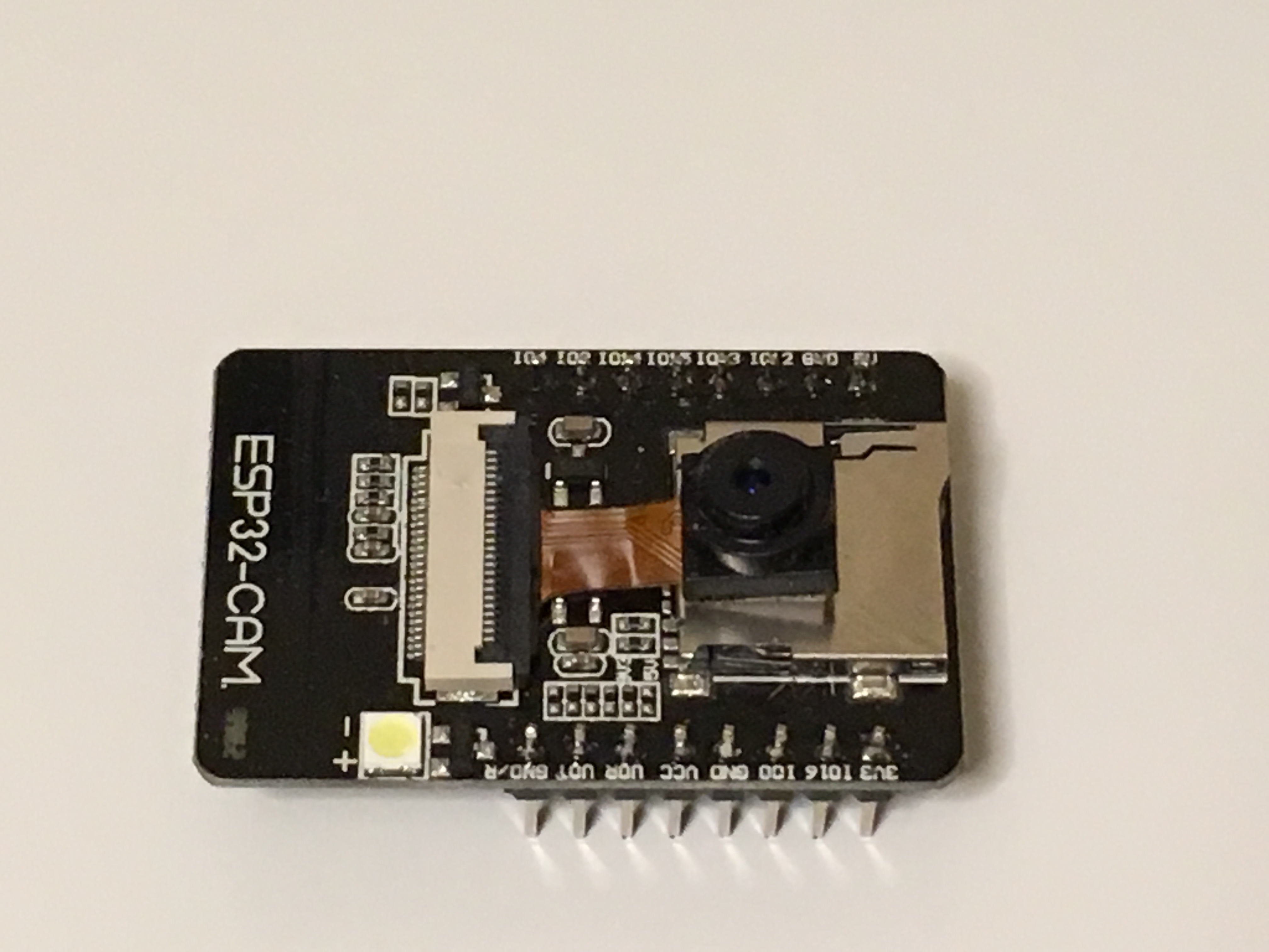
A note about the ESP32-CAM, so far I have run into one that was a little glitchy, it would be unstable and freeze/reset randomly. These ESP32-CAM boards are pretty cheap so I would grab a couple from different vendors, they are common to find on Amazon. They also should come with the camera, double check that it does.
Here are the three main parts and some links:
| ESP32-CAM (the ESP32-CAM board plus camera, I have had good luck with HiLetgo) | |
| + | https://www.amazon.com/HiLetgo-ESP32-CAM-Development-Bluetooth-Raspberry/dp/B07RXPHYNM |
| + | https://www.amazon.com/ESP32-CAM-Bluetooth-Camera-Module-Development/dp/B07S5PVZKV |
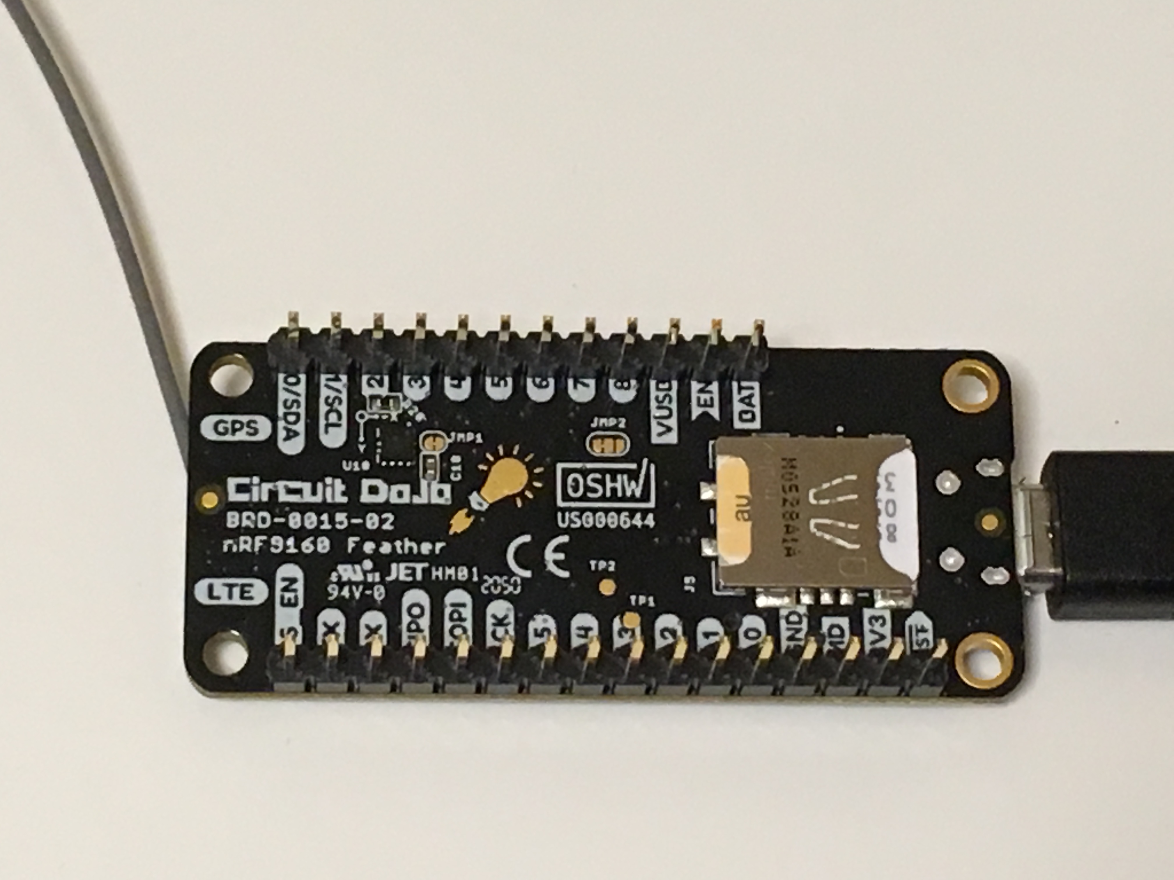
| Feather nRF9160 (board containing the new LTE radio from Nordic) | |
| https://www.jaredwolff.com/store/nrf9160-feather/ | |
| FTDI 3V3 cable (to program the ESP32-CAM, make sure it is 3V3) | |
| https://www.amazon.com/Converter-Terminated-Galileo-BeagleBone-Minnowboard/dp/B06ZYPLFNB | |
| https://www.digikey.com/en/products/detail/ftdi-future-technology-devices-international-ltd/TTL-234X-3V3/6823715 | |
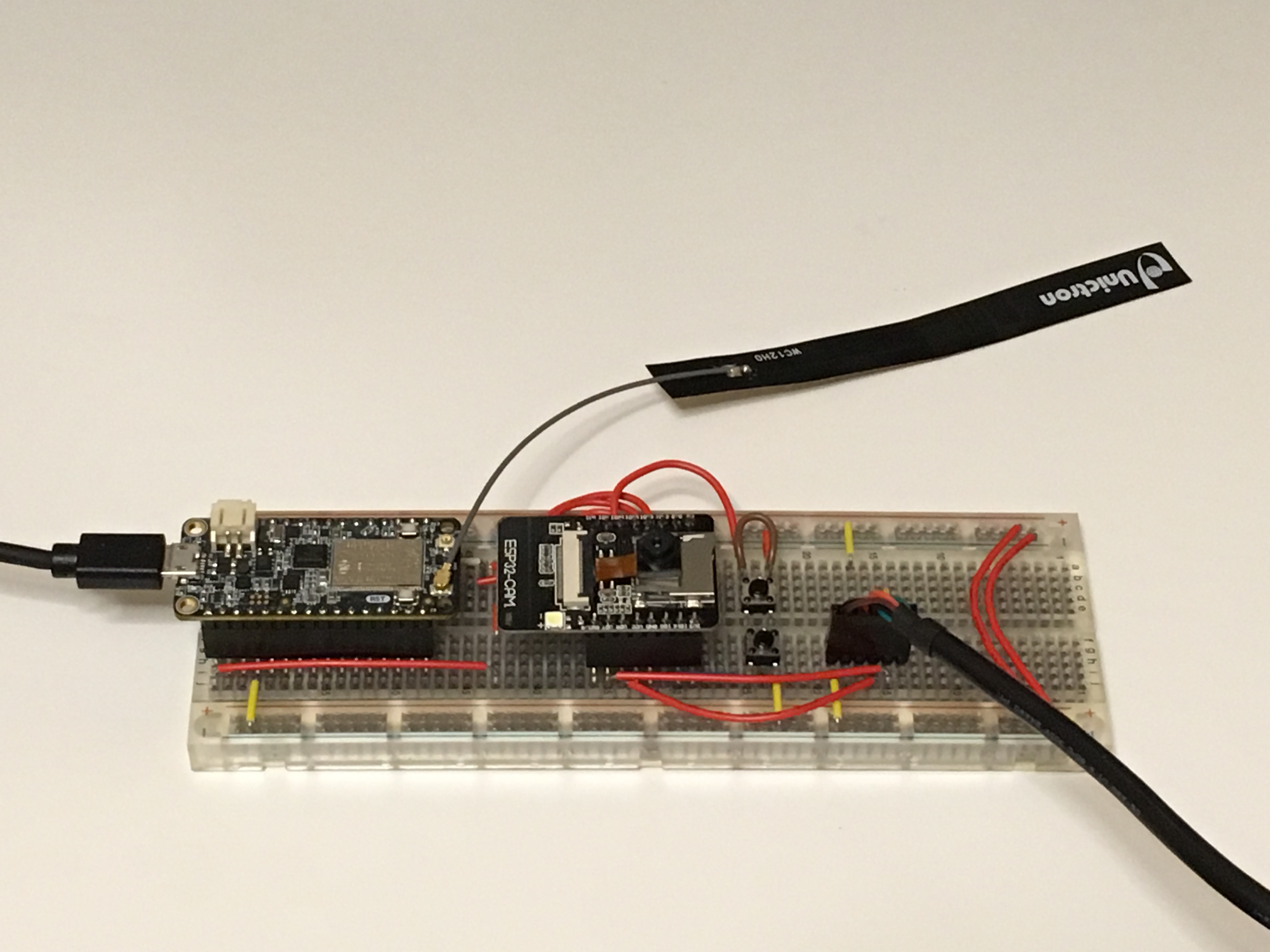
Here is how to wire it all up. There are some pictures to show the wiring if its easier to visualize, and below the pictures are tables with the pinout details.
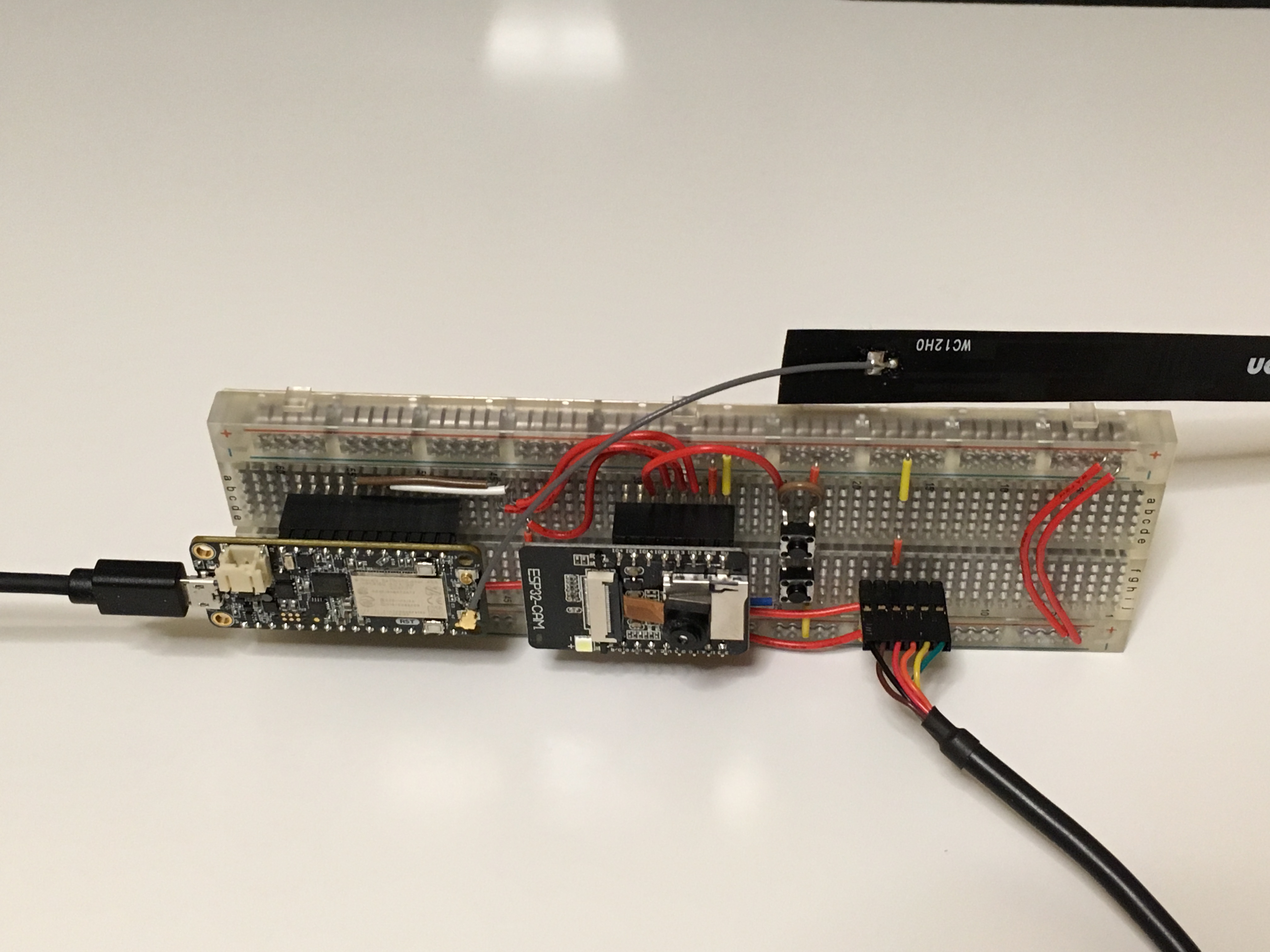
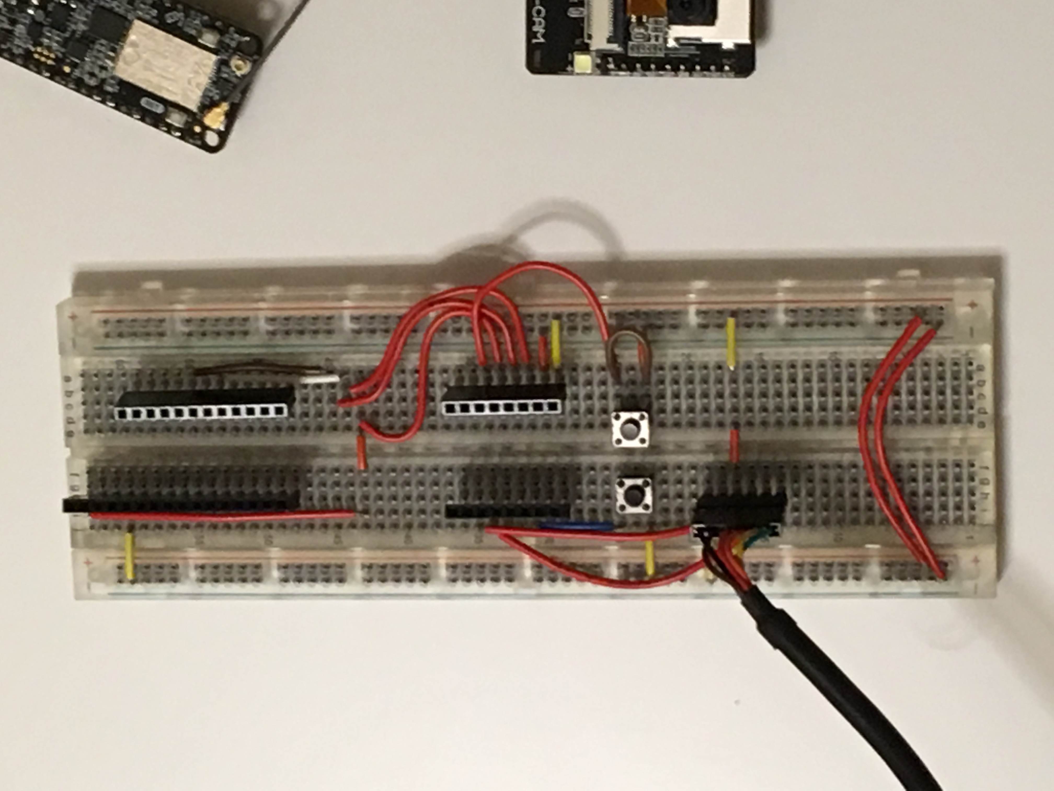
There are two buttons also visible, the top button is a “take picture” button, shorted so pictures are automatically taken. The bottom button is the “bootloader” button. Press this button and hold it while pressing the reset button (on the bottom side of the ESP32-CAM board). After the ESP32-CAM reset button is pressed release the “bootloader” button. Wiring between the nRF9160 and the ESP32-CAM and pinout descriptions is shown below.
| Feather nRF9160 | ESP32-CAM | ||
| Pin | Desciption | Pin | Desciption |
| RST | reset | IO15 | nRF9160 reset |
| D5 | UART2 RX | IO12 | UART TX |
| D7 | UART2 TX | IO13 | UART RX |
| Feather nRF9160 | ||
| Pin | Desciption | Info |
| GND | ground | connect to the common ground |
| RST | reset | connect to ESP32-CAM pin IO015 |
| D5 | UART2 RX | connect to ESP32-CAM pin IO12 |
| D7 | UART2 TX | connect to ESP32-CAM pin IO13 |
| ESP32-CAM | ||
| Pin | Desciption | Info |
| 5V0 | 5.0v power input | connect to FTDI pin 3 (red) |
| GND | GND | connect to the common ground |
| U0R | UART0 RX | connect to FTDI pin 4 (orange) |
| U0T | UART0 TX | connect to FTDI pin 5 (yellow) |
| IO0 | GPIO D0 | bootloader enable pin, active low |
| IO12 | GPIO D12 | connect to nRF9160 pin D5 |
| IO13 | GPIO D13 | connect to nRF9160 pin D7 |
| IO14 | GPIO D14 | “take picture” switch, active low |
| IO14 | GPIO D15 | connect to nRF9160 pin RST |
| FTDI 3V3 6-pin connector | ||
| Pin | Description | Info |
| 1 (black) | GND | connect to the common ground |
| 2 (brown) | CTS# | not used |
| 3 (red) | 5V0 | connect to ESP32-CAM 5V0 pin |
| 4 (orange) | TXD | connect to ESP32-CAM U0R pin |
| 5 (yellow) | RXD | connect to ESP32-CAM U0T pin |
| 6 (green) | RTS# | not used |
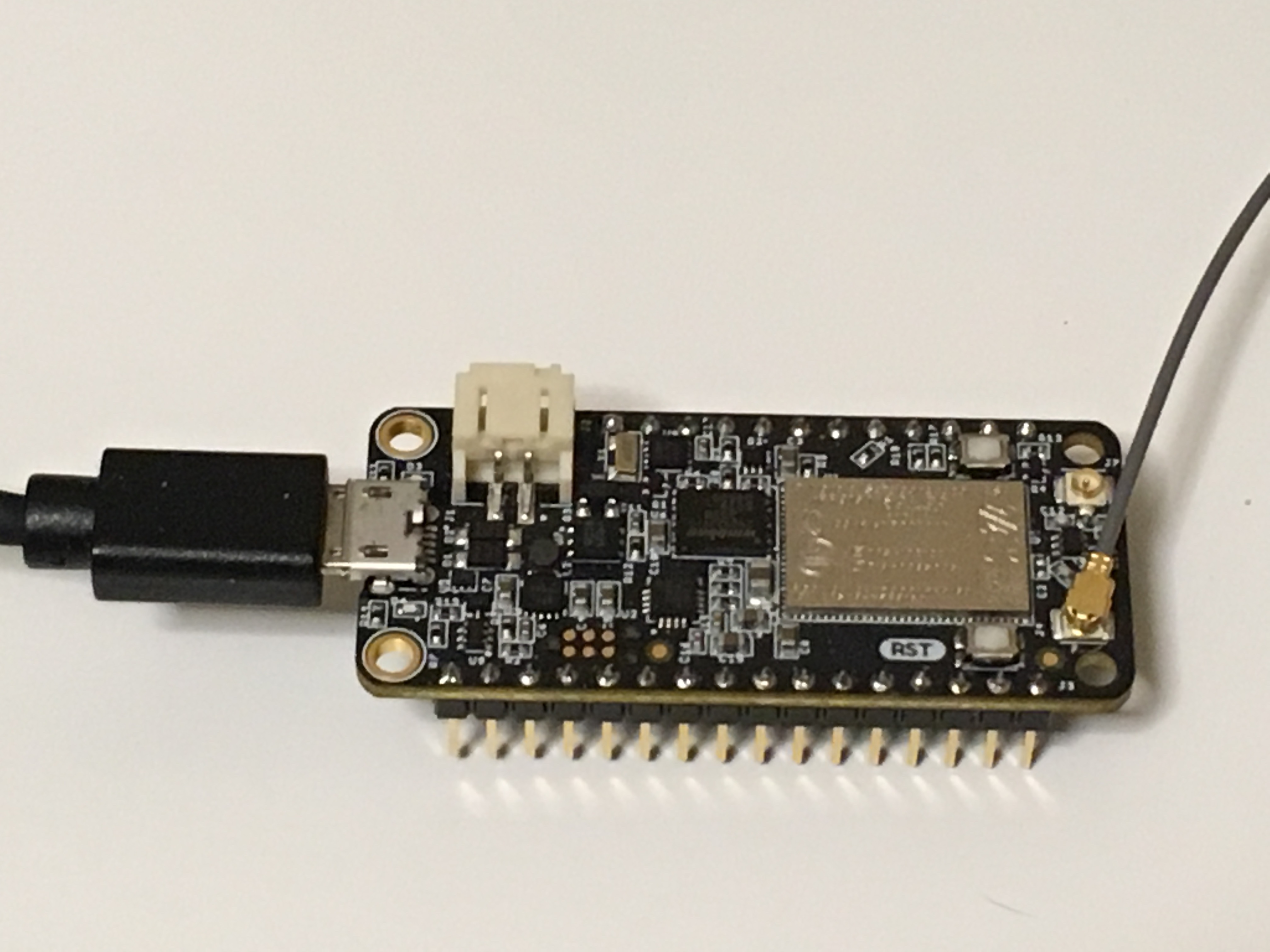
Please do make sure the FTDI cable you are using is a 3.3v version. The signal lines will be 3.3v but red pin will still have 5.0v on it. We will power the ESP32-CAM 3V3 regulator from with the 5.0v on the FTDI cable. Also notice the nRF9160 has its own USB cable, it is powered from that cable. Since there is no pin on the Feather nRF9160 that we can use to power the Feather nRF9160 we are powering the Feather nRF9160 with a second USB cable.
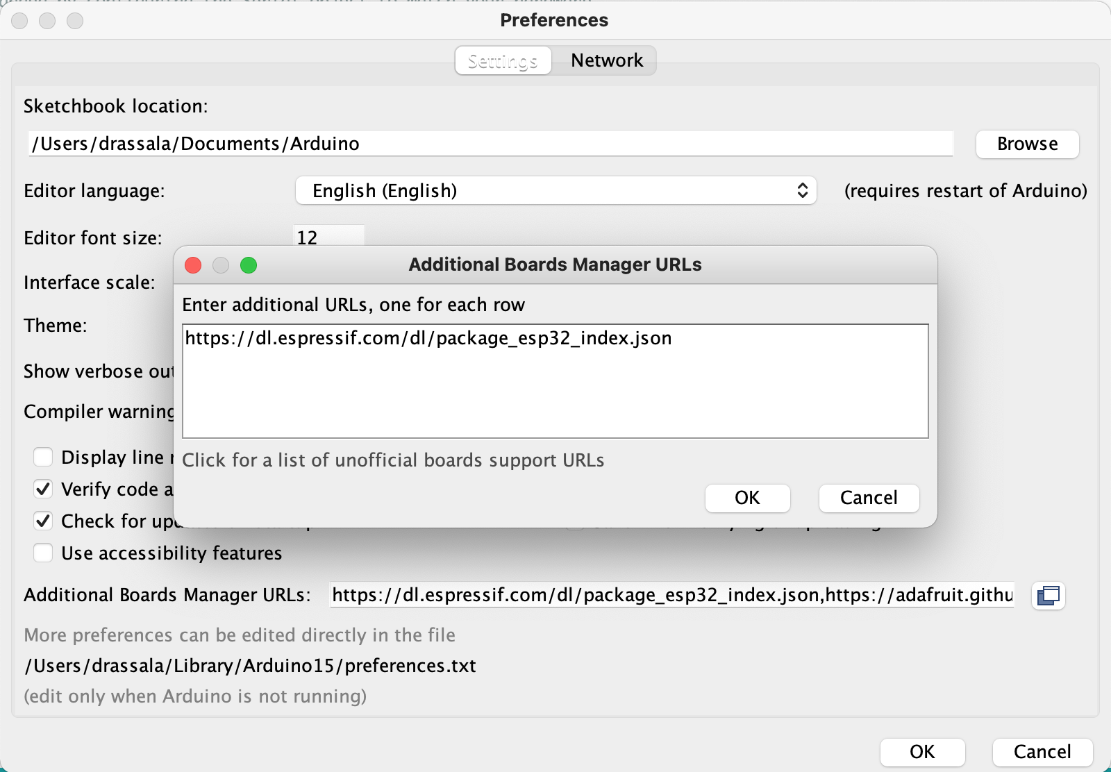
The Arduino hardware support and some libraries will also need to be installed, to install the Arduino library for the ESP32-CAM open up the Arduino preferences add the following URL to the “Additional Boards Manager URLs box, there is a button to the right that will open up a text box to easily add more than one URL.
https://dl.espressif.com/dl/package_esp32_index.json
Press the “OK” buttons and then open up the “Board Manger” from the “Tools” “board” menu.
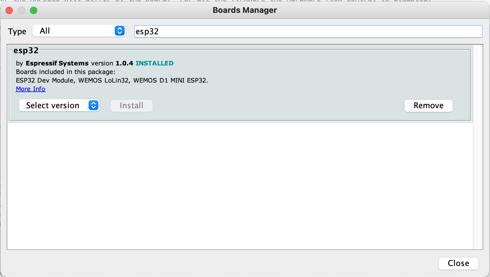
Type “esp32” into the search box and install the “esp32” board package. This will add support for many ESP32 based boards including the “AI Thinker ESP32-CAM.” the board that we are working with. Be sure to select the board after installing it.
There are a couple other libraries that can be installed through the “Library Manager” if they are not installed, these are:
+ StreamDebugger
+ Time
Additionally, we use TinyGSM, but the version in the Library Manager does not have nRF9160 support, please download that from here and extract the contents into the “library” folder, generally located in “My Documents/Arduino/libraries”.
https://www.drassal.net/filestore/esp32_nrf9160_camera_http_20210203/TinyGSM_20210203.zip
Also grab the Arduino sketch from the below link, unzip this in your Arduino sketch folder.
These next steps will involve getting the Feather nRF9160 programmed so it will work with TinyGSM (as a AT command driven serial LTE modem). Getting the nRF9160 programmed might take a little patience. I found the easiest way is to use “nrfjprog” from Nordic, however, there are GUI based programming tools available also.
I have not had luck with the bootloader for the Feather nRF9160 as the hex file we will load is a little too big. We may need to use a hardware JLink programmer, or an nRF9160DK, I also hear an nRF53 series DK will also work. A 6-pin TagConnect cable will also be required to connect the Feather nRF9160 programming pins to the programmer.
For the TagConnect, there are a couple routes to go, this cable should connect directly to the nRF9160DK but I have not personally tested it. Also the smaller thinner wires might break easier with heavy use.
The connector that I have is the the following, I made an adapter board so I can use it for other projects in the future. The pins on this connector are routed straight through, pin-for-pin. There are links to a couple other useful items that can be used to make the adapter board.
https://www.tag-connect.com/product/tc2030-idc-nl
https://www.adafruit.com/product/2743
https://www.adafruit.com/product/1675
The TagConnect cables are not cheap, but are very useful to have around, I am seeing more and more development boards with TagConnect pads. If you are buying one I would recommend grabbing both of the generic 6-pin and 10-pin versions for future use, these two links below.
https://www.tag-connect.com/product/tc2030-idc-nl
https://www.tag-connect.com/product/tc2050-idc-nl-10-pin-no-legs-cable-with-ribbon-connector
There two files to program, one is to update the nRF9160’s baseband (modem) firmware, the other is to program the actual nRF9160’s main MCU. If the nRF9160DK is being used instead of the Feather nRF9160 there is one additional hex file to program for the nRF9160DK’s “board controller” nRF52840.
https://www.drassal.net/filestore/esp32_nrf9160_camera_http_20210203/nrf9160_baseband_20210203.zip
https://www.drassal.net/filestore/esp32_nrf9160_camera_http_20210203/nrf9160_firmware_20210203.zip
Detailed instructions for programming the nRF9160 is a discussion in itself and I will write up another post with all the details about how to program the three types of nRF9160 boards that I have run into so far.
There are details in the baseband zip file on how to program the baseband, along with the firmware files in the firmware zip file. For the firmware files there are many to choose from, for the Feather nRF9160 to program it through the nrfjprog utility or the GUI programmer) it would be serial_lte_modem_circuitdojo_feather_nrf9160_115200_merged.hex, 115200 referring to the speed the UART is running at.
For the time being the programming of the nRF9160 is a little above the scope of this guide and will cover it in another post and link to it here when that post is finished. For now try to search online to get setup for programming.
Setting up the sketch
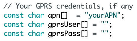
Lets go back now to the Arduino IDE and load the sketch, there are a couple things we will need to setup. First will be the APN information for your SIM card, the APN name and then authentication if required, TinyGSM is setup to use CHAP now, it can be changed over to PAP if necessary.
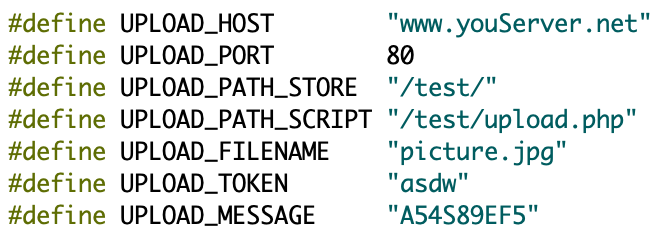
Next we need to decide where we are going to send the images to, this is setup at the top of the sketch. The “UPLOAD_TOKEN” and “UPLOAD_MESSAGE” are not used, but left in as placeholders for some kind of authentication system later.
Here is a simple upload.php that can receive the uploaded images.
<?php
$uploadfile = "";
echo "Receiving file [";
echo $_FILES["imageFile"]["name"];
echo "]\r\n";
if(strlen(basename($_FILES["imageFile"]["name"])) > 0)
{
 $uploadfile = basename($_FILES["imageFile"]["name"]);
 if(move_uploaded_file($_FILES["imageFile"]["tmp_name"], $uploadfile))
 {
 echo "saved ";
 } else {
 echo "error moving file";
 }
} else {
 echo "error image data does not exist";
}
?>
After this build and program the ESP32-CAM. If everything is setup right you should see the Feather nRF9160 connect to the LTE network and see images being uploaded. It takes time to connect (6 seconds alone for the Feather nRF9160 hardware reset to finish).
There is a lot more detail I want to add to this but going to post this guide up as it is now and add the rest of the information in a little bit. The required files and source code are all linked above and that is mostly what I wanted to get posted up while I finish fixing up this guide.