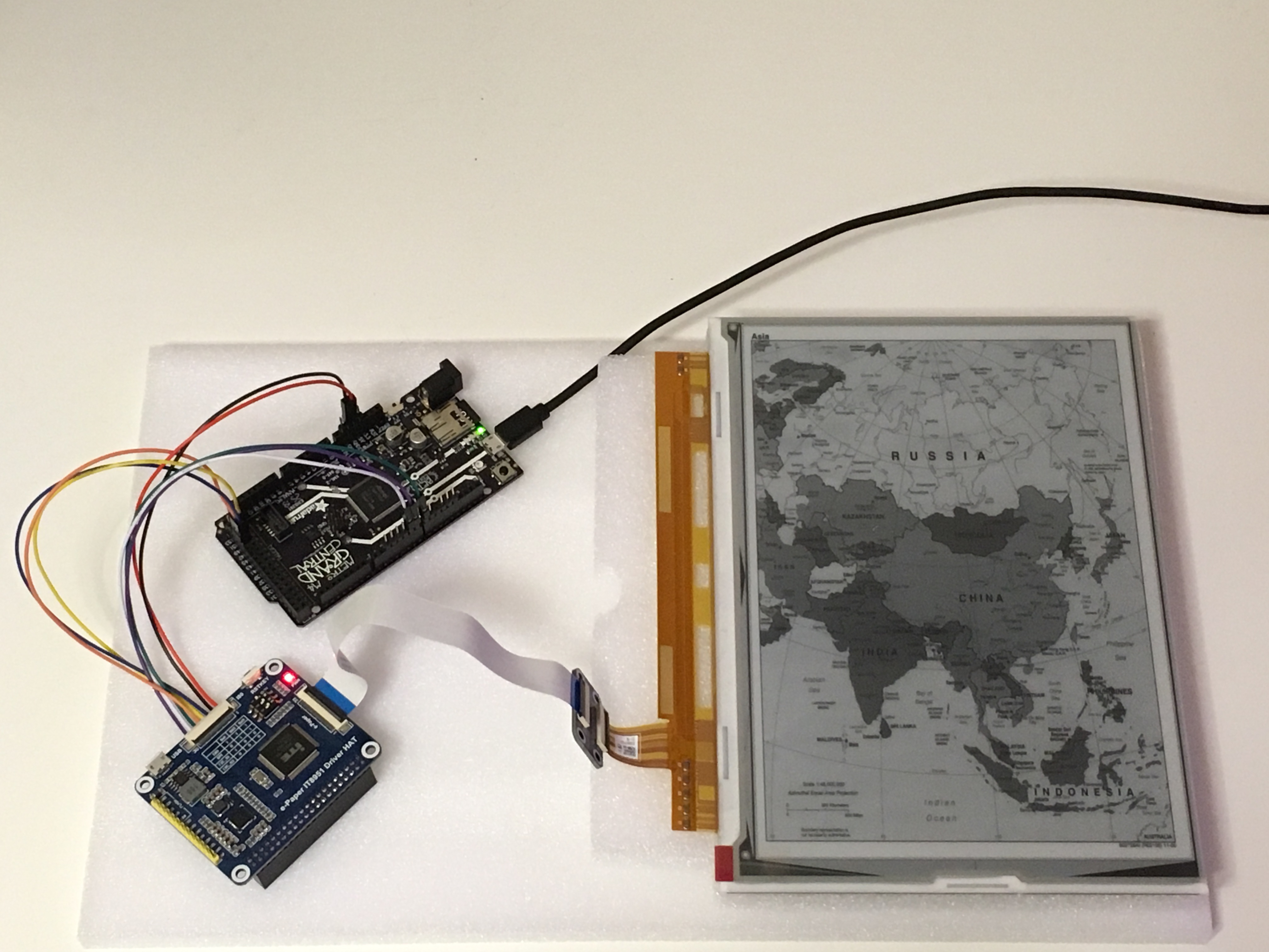
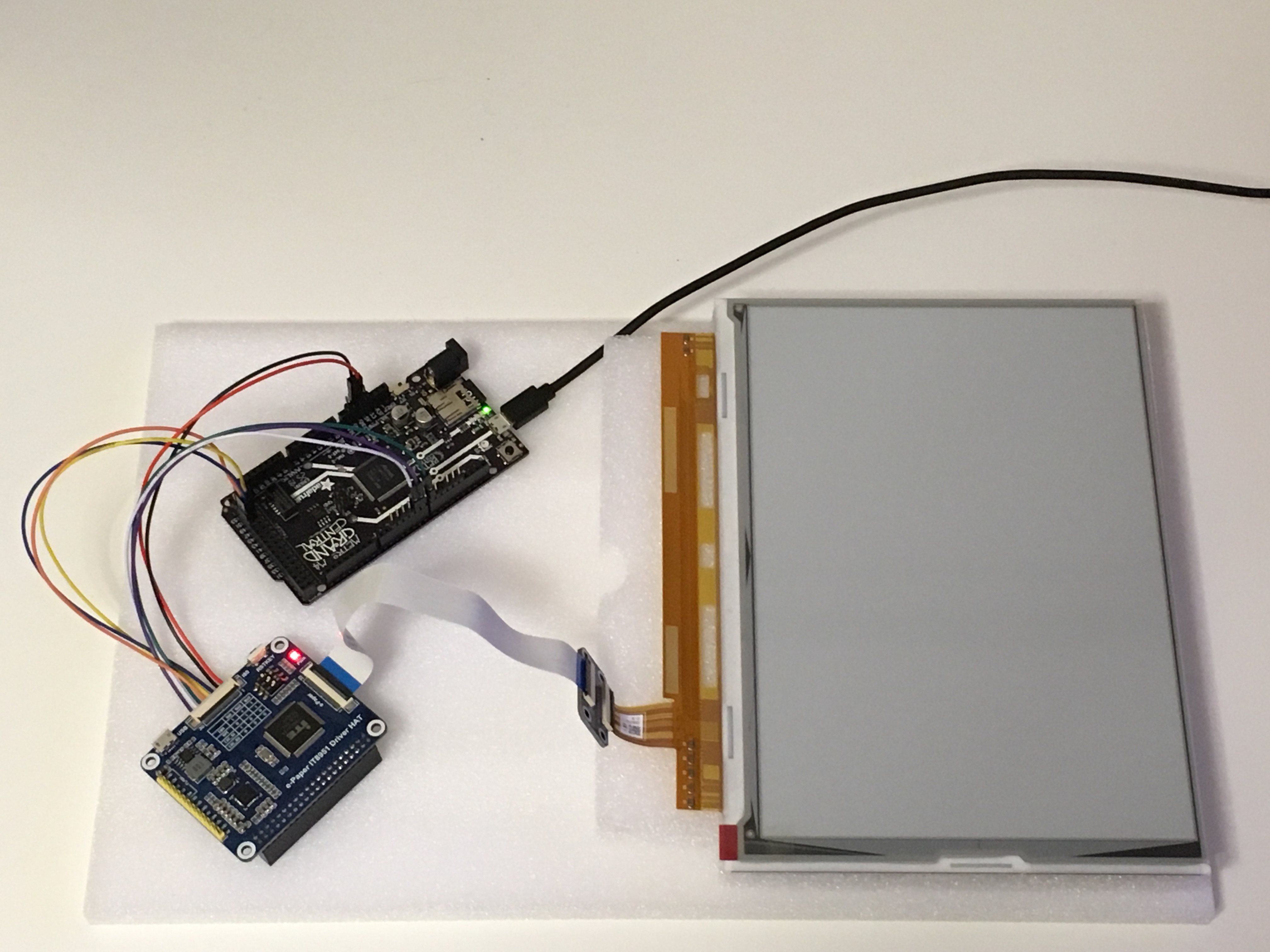
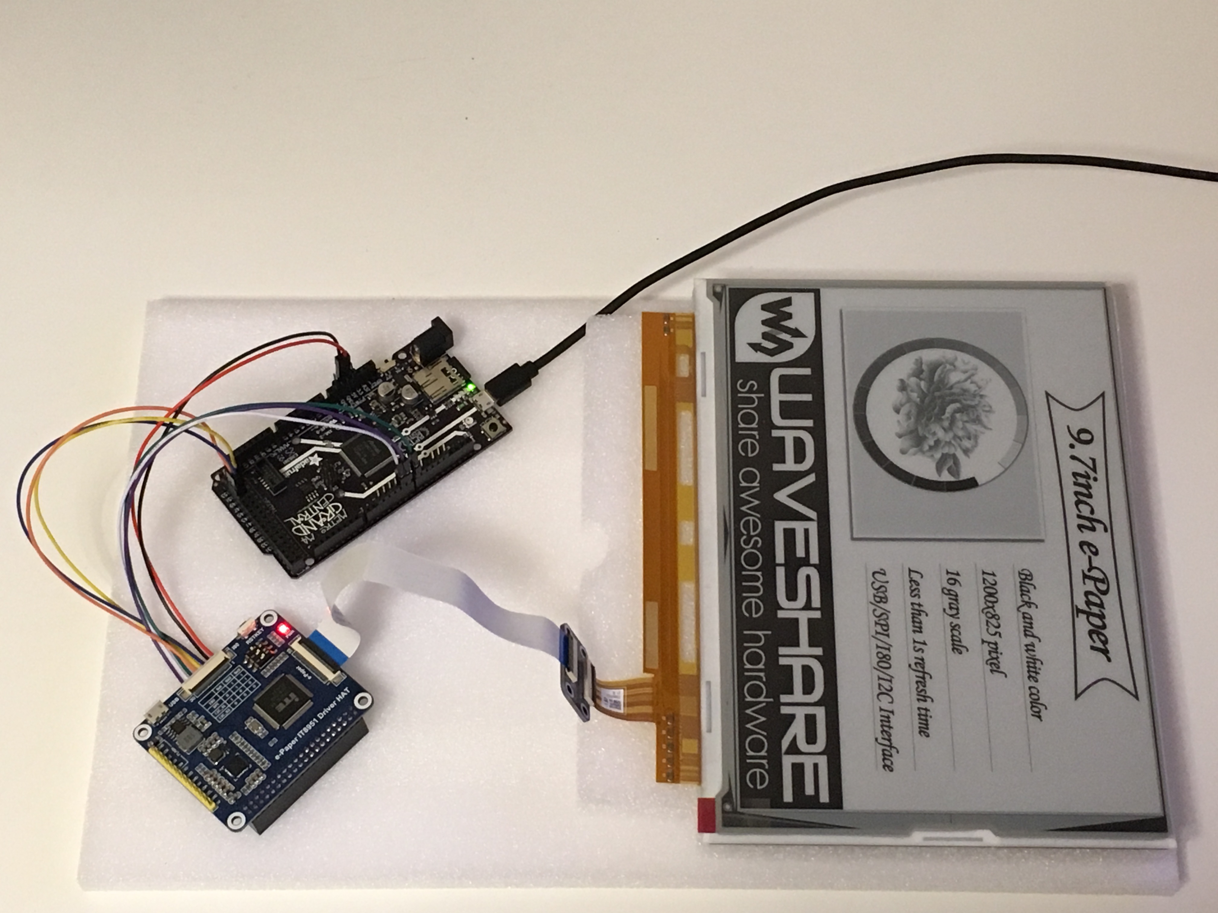
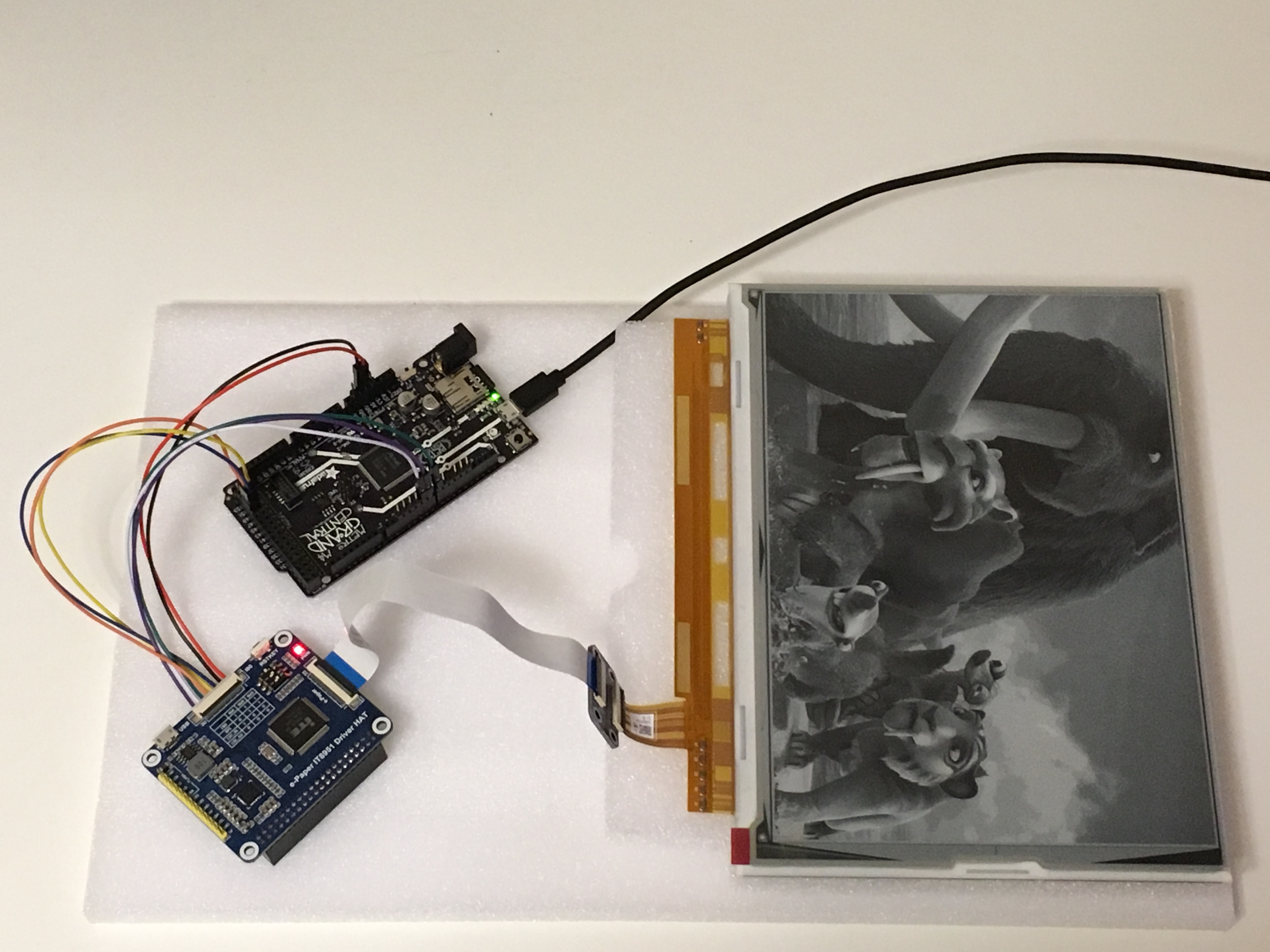
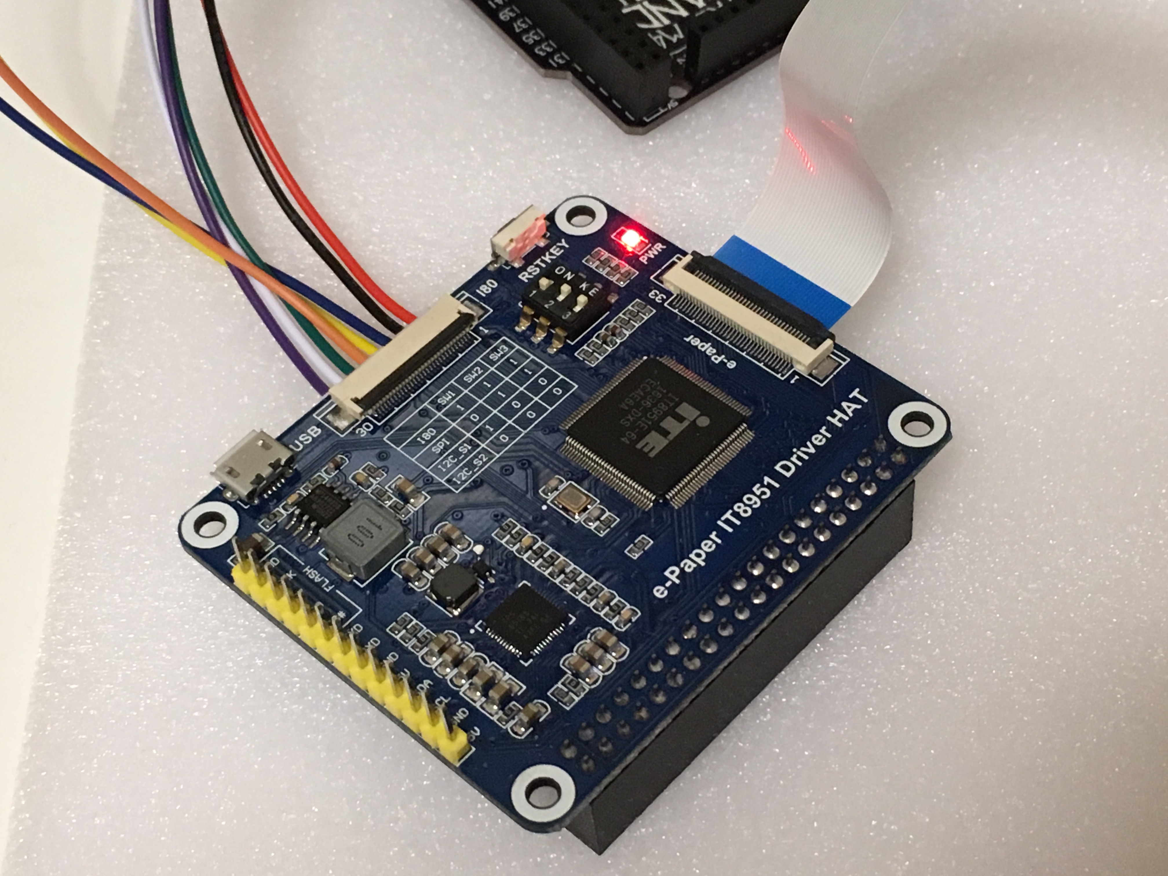
Had some fun playing around with an e-paper display this last weekend. Chose the Adafruit Grand Central M4 (SAM51) because of the large amount of flash and SRAM, but alas it was not enough SRAM to do what I wanted to do. This is a GDEP097TC2 e-paper display with a parallel interface, hence the use of the IT9851 controller. This is a really beautiful display at a diagonal size of 9.7″ but a high resolution of 1200W x 825H pixels. As seen in the pictures below it can display 16 shades of grey.
The IT8951 has the capability of updating very quickly, however we are a little limited with SPI for now. I plan to get the I80 (parallel interface) working on the IT9851 later, but I don’t have the flat cable and connectors right now to match the I80 interface connector. I haven’t looked into partial updates, but I believe this is also possible if there is enough SRAM to create an image buffer. I am hoping to do this after I receive an SDRAM module.
Was planning on creating a buffer in SRAM for the display so that the image could be edited then displayed, but due to how the IT9851 accepts data, its 4 bits per pixel (16 shades of grey) or half a byte per pixel. Calculating this out the display is 1200W x 825H which comes out to 990,000 pixels, and we would need a buffer of 990,000 / 2 = 495,000 bytes. The Grand Central M4 only has 256k of SRAM. This is defiantly out, at least for now. I have an SDRAM module on order that I am going to use to expand the memory available for a later project, listing that below if there is any interest.
https://www.waveshare.com/sdram-board-b.htm
For this the following parts are used:
+ Adafruit Grand Central M4
+ WaveShare 1200×825, 9.7inch E-Ink display HAT for Raspberry Pi
+ 2GB SD card
The Adafruit Grand Central M4 is really handy to have around for various Arduino (or Circuit Python) projects where you don’t want to worry about flash and SRAM limits (most of the time). I would recommend picking a couple up if you are ordering anything from Adafruit and want a beefy board around to do projects in Arduino or Circuit Python. I have not tried Circuit Python yet, but it has peaked my interest on a few occasions.
Even though we can’t load the entire image into SRAM, no worry we will work around it for this project. We have an SD card slot on the Adafruit Grand Central M4 so we are going to use a 2GB SD card to hold the image data for us and send it to the IT8951 as we read it from the SD card. There is a small buffer of 1200 * 54 = 64800 bytes (57 lines) to speed this up. I believe the SD card functions are limited to 65k due to the use of a uint16_t in the read function for size.
For whatever reason I can’t figure out why the image I load into the IT8951 is reversed, it could be that the image data is reversed in the BMP file, anyway I did some fancy coding to reverse the pixels of each line as its sent to the IT8951. This is a little wonky, but works for now. Maybe I can somehow get the IT8951 to load the memory backwards, but I haven’t investigated too far into the IT8951’s inner workings yet.
The image data is in BMP format and has to be formatted specifically, more detail is on the WaveShare wiki at the following webpage.
https://www.waveshare.com/wiki/9.7inch_e-Paper_HAT
However, we are assuming these images are formatted correctly and we will go ahead and use the provided images and copy them to an SD card. I would recommend a 2GB SD card, not sure if others will work. I formatted it to FAT16, not sure if FAT32 will work so I recommend using a FAT16 format. You could go about and find images, crop them, etc, but I am providing the three that I used for this project in the zip file below.
Let me note that I have not really cleaned up the code for reasons that I might use those function in the future or just didn’t get around to cleaning some parts. You will find some function are not connected to anything but were used during the development cycle to test things.
m4_GDEP097TC2_hwspi_sd_202102202200.zip
Unzip this above file and place it in your Arduino sketch folder. You should already have Arduino setup to use the Adafruit M4 Grand Central. If not, you can review the setup procedure on their website. The files in the “images_for_sd_card” should be copied to the SD card, then they can be deleted from the Arduino project folder if you wish, they don’t appear to harm anything by leaving them there. Remember to change your board type to “Adafruit Grand Central M4 (SAM51)” in the tools menu. There are no extra libraries required.
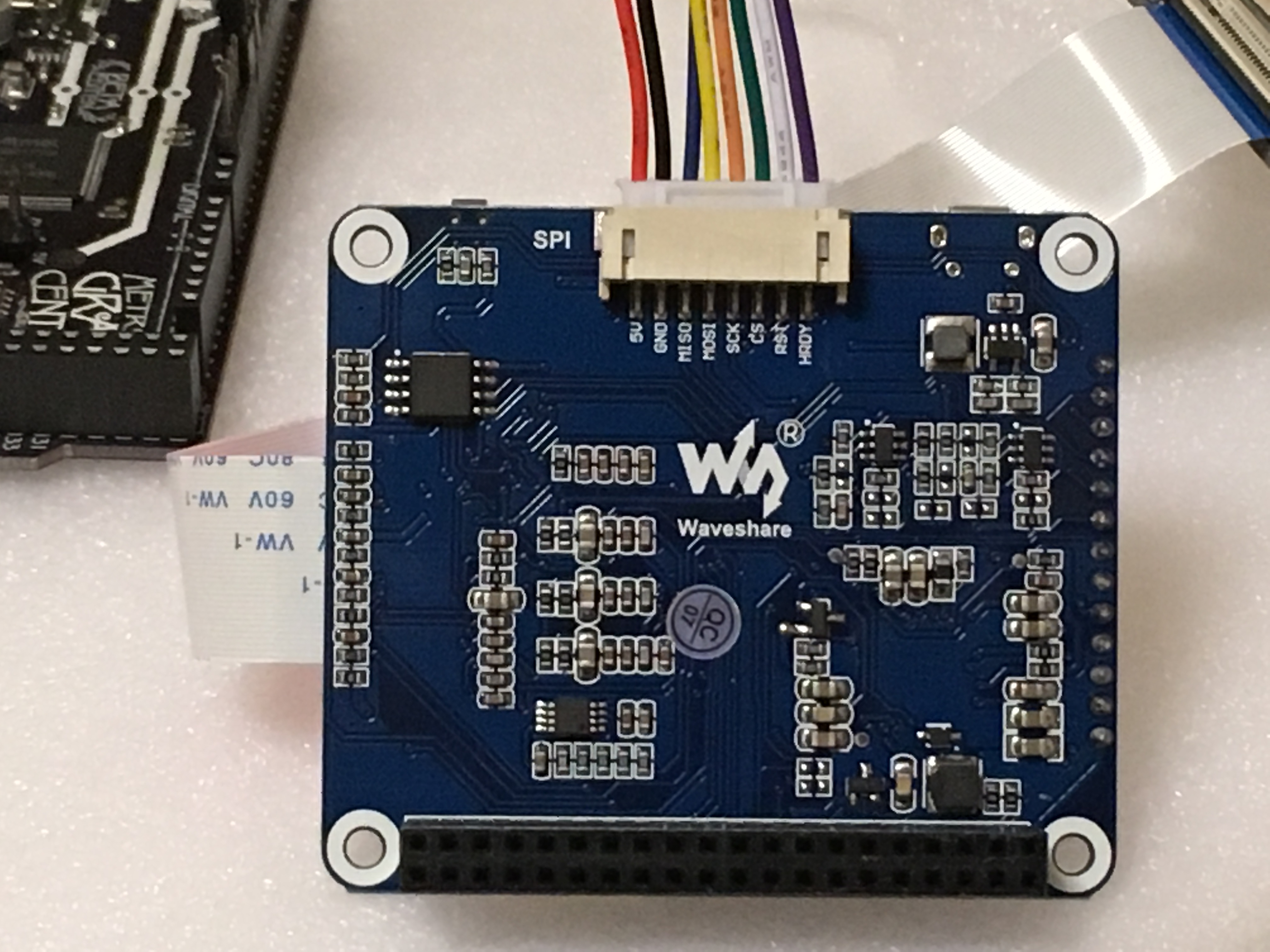
I first wrote this with the software SPI library, hence it is still present, but switched over to hardware SPI later on, it works much smoother. The IT9851 supports up to 24Mhz SPI speed, but high speed SPI does not appear to like these long wires, connectors, and other stuff, so its throttled back to 12Mhz, do experiment with it though if you wish. Also it is purposely not using the default SPI interface to leave it free for other things, the SERCOM6 interface is being used for the SPI interface, it is trivial to change it back by changing the various options in the software_spi.h file as shown below, uncomment only one of these.
//#define USE_SOFTWARE_SPI 1
//#define USE_HARDWARE_SPI_DEFAULT 1
#define USE_HARDWARE_SPI_SERCOM6 1
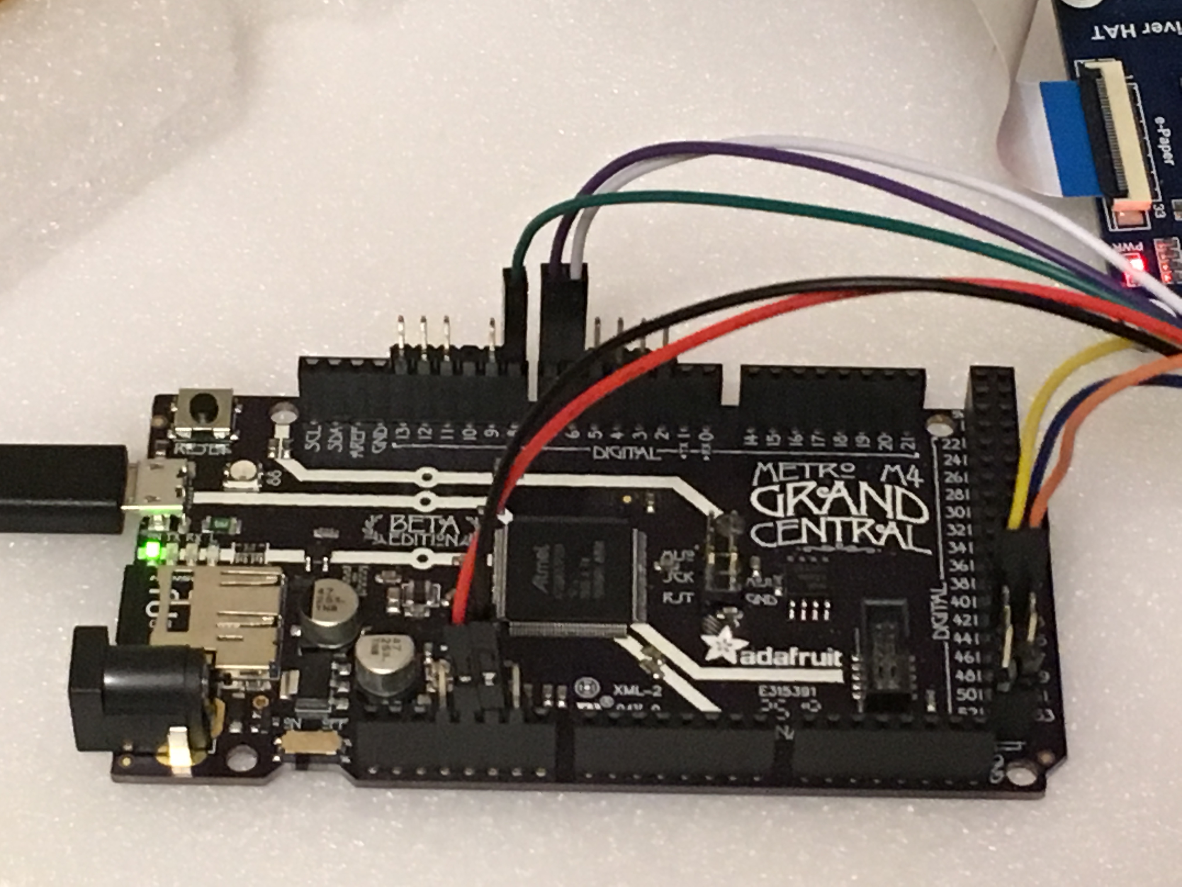
Now on to the wiring, it is trivial to also find the wiring information in the files software_spi.h and IT8951.h files. The wiring is listed below, also note the IT8951 board DOES need 5V for power, but the logic is 3.3V.
| Arduino digital IO | function |
|---|---|
| 6 | IT8951 RST |
| 7 | IT8951 HRDY |
| 8 | IT8951 CS |
| 47 | IT8951 MISO |
| 48 | IT8951 MOSI |
| 49 | IT8951 CLK |
| 5V | IT8951 5V |
| GND | IT8951 GND |
Do make sure you are connecting to the “digital” pins and not the “analog” pins as I did the first time and couldn’t figure out why it wasn’t working.
That’s about it, connect things up, insert the SD card, load the Arduino code and that should be about it. Below are some more pictures.

