
I started working with a CC1310 at work again and we have a need to be able to update the CC1310 MCU flash memory through the JTAG (SWD) connection from the STM32F401Re main MCU.
The board that I have to develop this on is not quite the CC1310, but a CC1350, which is close enough to do the code development, then port it to the CC1310 after.
What is a CC1310? This is an ARM based sub-gigahertz RF microcontroller by Texas Instruments that enables communication in the 779-928 MHz range. More detailed information is on TI’s website at this link.
The CC1350 is nearly identical with the addition of a 2.4Ghz radio as well to allow communication over BLE (or other protocols).
The CC1310 from TI is a nice low power RF part, I wish it offered more than 128K FLASH. It barely has enough space to run the wireless stack and some simple application logic, much less than is required.
Initially we wanted to go with the CC1350 as it has both radios in it, but, the severe limitation of FLASH to 128K does not allow both stacks to coexist together. The sub-giga stack that we are using takes up nearly the full 128K as is… which leaves no room for a BLE stack.
The question that bothers us is how to field update this MCU after distribution to the customer. There is a built in ROM boot loader which is able to update the firmware, but it would be nice to be able to recover the MCU from whatever state it is in… make it unbrickable. Therefore connecting the STM32F401RE to the CC1310 with a SWD connection would allow the STM32F401RE to issue JTAG commands to the CC1310 just like a debug interface, and reprogram the it as well.
The trouble, the CC1310’s FLASH can not be directly accessed over JTAG, it turns out that only the MCU itself can reprogram the FLASH. However, we can load something into SRAM and direct the CC1310 to execute it by JTAG. Therefore if we load some simple logic into SRAM, along with a chunk of data to be programmed into FLASH this becomes possible. With only 20K of SRAM on the CC1310 (CC1350) this becomes nearly impossible to run any really complicated logic in SRAM, but all we need to do is copy something from SRAM into FLASH. Ideally if we made some logic that allowed reception of data over the USART to be written into FLASH that might go much faster, which is now the ROM boot loader works to my knowledge.
In order to facilitate this, I needed to do some learning of how to write code for the CC1310 (CC1350) that didn’t require TI’s RTOS to run, even completely stripped down the RTOS will not fit in SRAM.
I has a lot of trouble locating information on how to write code for the CC1310 (CC1350) outside of the RTOS, and it is not officially supported by TI, so I would like to share the progress of this project as it may provide assistance to others in the future.
First of all the needed tools and software list:
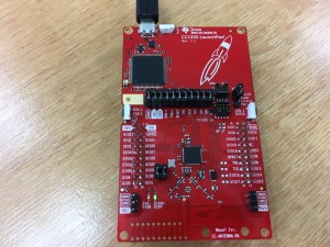
- CC1350 Launchpad (or CC1310 LaunchPad, there might be some differences)
- TI’s Code Composer Studio 7 (a free download, I will be using the Mac OSX version but Windows should be similar)
- tidrivers_cc13xx_cc26xx_2_20_01_10 drivers (included with the tirtos_cc13xx_cc26xx_2_20_01_08 package available here)
About the tidrivers, they will most likely be auto installed with Code Composer Studio 7 (CCS7), and a different version most likely will work, but be sure to correct the paths in some of the instructions to match. If the paths are not correct there will be trouble with building and linking since the required files can not be found.
After CCS7 is installed, open it and let it update any files it recommends. CCS7 is basically a highly customized version of Eclipse, but the nice thing is that all tool chains and required files are self contained, at least on the OSX version.
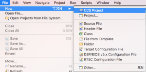
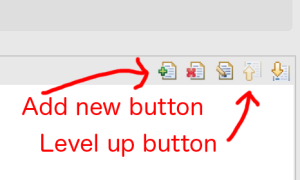
Now that CCS7 is all updated create a new CCS project from the file menu.
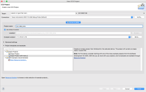
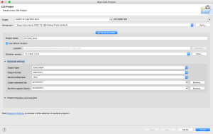
This will bring up a new project details dialog, fill in the details as shown, feel free to rename the project to something of your liking.
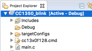
Now we should have a new project created as shown on the right.
Open up the main.c file by double clicking on it and we will add the code necessary to blink the LEDs on the LaunchPad.
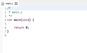
Shown to the left is what your main.c should look like after just creating the project, just the main function.
What we are going to create is a simple LED blink program. It is simple to turn on and off an LED with just a while loop with a delay loop, but, a while loop is not very feasible for a real project so we are going to create it with a timer interrupt.
Let’s create the function to first setup the timer.
/*
 *  ======== timer_setup ========
 *  Function to setup the GPT0 timer.
 *  Using GPT0 timer A, periodic mode
 *  Interrupt callback to ISR_TimerInterrupt_Handler
 */
void timer_setup(void)
{
    // Power on periperal domain
    PRCMPowerDomainOn(PRCM_DOMAIN_PERIPH);
    PRCMLoadSet();
    while ( !PRCMLoadGet() );

    // Power on the TIMER0 peripheral
    PRCMPeripheralRunEnable(PRCM_PERIPH_TIMER0);
    PRCMLoadSet();
    while ( !PRCMLoadGet() );

    // Enable TIMER0 to continue counting while the MCU sleeps
    PRCMPeripheralSleepEnable(PRCM_PERIPH_TIMER0);

    // Configure the TIMER0
    TimerConfigure(GPT0_BASE, TIMER_CFG_A_PERIODIC);
    // Set initial timer value
    TimerLoadSet(GPT0_BASE, TIMER_A, 0xFFFFFF);
    // Set prescaler
    TimerPrescaleSet(GPT0_BASE, TIMER_A, 0x000000FF);//255
    // Timer to count on positive clock edge
    TimerEventControl(GPT0_BASE,TIMER_A,TIMER_EVENT_POS_EDGE);
    // Be sure the interrupt is clear to start
    TimerIntClear(GPT0_BASE,TIMER_TIMA_TIMEOUT);
    // Assign the interrupt handler
    TimerIntRegister(GPT0_BASE, TIMER_A, ISR_TimerInterrupt_Handler);
    // Enable the interrupt
    TimerIntEnable(GPT0_BASE,TIMER_TIMA_TIMEOUT);
    // Enable the timer
    TimerEnable(GPT0_BASE,TIMER_A);
}
Next lets add the interrupt handler function.
/*
 *  ======== ISR_TimerInterrupt_Handler ========
 *  Interrupt handler to service the TIMER_TIMA_TIMEOUT interrupt.
 */
void ISR_TimerInterrupt_Handler(void)
{
    // clear interrupt flag
    TimerIntClear(GPT0_BASE, TIMER_TIMA_TIMEOUT);
    // toggle the red LED
    GPIO_toggleDio(IOID_6);
    // toggle the green LED
    GPIO_toggleDio(IOID_7);
}
Add the function to setup the LEDs.
/*
 *  ======== led_setup ========
 *  Setup the red and green LEDs
 */
void led_setup(void)
{
    // Power on periperal domain
    PRCMPowerDomainOn(PRCM_DOMAIN_PERIPH);
    while(PRCMPowerDomainStatus(PRCM_DOMAIN_PERIPH) != PRCM_DOMAIN_POWER_ON);

    // Power on the GPIO peripheral
    PRCMPeripheralRunEnable(PRCM_PERIPH_GPIO);
    PRCMLoadSet();
    while ( !PRCMLoadGet() );

    // enable output for the red LED
    GPIO_setOutputEnableDio(IOID_6, GPIO_OUTPUT_ENABLE);
    // turn on the red LED
    GPIO_setDio(IOID_6);

    // enable output for the green LED
    GPIO_setOutputEnableDio(IOID_7, GPIO_OUTPUT_ENABLE);
    //turn off the green LED
    GPIO_clearDio(IOID_7);
}
Add the main function.
/*
 *  ======== main ========
 *  Main function
 */
int main(void) {
    // setup the LEDs
    led_setup();

    // setup the timer
    timer_setup();

    // enable the master interrupt
    IntMasterEnable();

    // loop forever waiting for an interrupt
    for(;;);

    return 0;
}
Take care of defines and includes at the top of main.c.
#include <stdlib.h>
#include "driverlib/gpio.h"
#include "driverlib/ioc.h"
#include "driverlib/prcm.h"
#include "driverlib/timer.h"
#include "driverlib/sys_ctrl.h"
#include "inc/hw_memmap.h"
#include "inc/hw_ints.h"

void led_setup(void);
void ISR_TimerInterrupt_Handler(void);
void timer_setup(void);
Putting it all together we have the complete main.c file.
/*
 * main.c
 */
#include <stdlib.h>
#include "driverlib/gpio.h"
#include "driverlib/ioc.h"
#include "driverlib/prcm.h"
#include "driverlib/timer.h"
#include "driverlib/sys_ctrl.h"
#include "inc/hw_memmap.h"
#include "inc/hw_ints.h"

void led_setup(void);
void ISR_TimerInterrupt_Handler(void);
void timer_setup(void);

/*
 *  ======== main ========
 *  Main function
 */
int main(void) {
    // setup the LEDs
    led_setup();

    // setup the timer
    timer_setup();

    // enable the master interrupt
    IntMasterEnable();

    // loop forever waiting for an interrupt
    for(;;);

    return 0;
}

/*
 *  ======== led_setup ========
 *  Setup the red and green LEDs
 */
void led_setup(void)
{
    // Power on periperal domain
    PRCMPowerDomainOn(PRCM_DOMAIN_PERIPH);
    while(PRCMPowerDomainStatus(PRCM_DOMAIN_PERIPH) != PRCM_DOMAIN_POWER_ON);

    // Power on the GPIO peripheral
    PRCMPeripheralRunEnable(PRCM_PERIPH_GPIO);
    PRCMLoadSet();
    while ( !PRCMLoadGet() );

    // enable output for the red LED
    GPIO_setOutputEnableDio(IOID_6, GPIO_OUTPUT_ENABLE);
    // turn on the red LED
    GPIO_setDio(IOID_6);

    // enable output for the green LED
    GPIO_setOutputEnableDio(IOID_7, GPIO_OUTPUT_ENABLE);
    //turn off the green LED
    GPIO_clearDio(IOID_7);
}

/*
 *  ======== ISR_TimerInterrupt_Handler ========
 *  Interrupt handler to service the TIMER_TIMA_TIMEOUT interrupt.
 */
void ISR_TimerInterrupt_Handler(void)
{
    // clear interrupt flag
    TimerIntClear(GPT0_BASE, TIMER_TIMA_TIMEOUT);
    // toggle the red LED
    GPIO_toggleDio(IOID_6);
    // toggle the green LED
    GPIO_toggleDio(IOID_7);
}

/*
 *  ======== timer_setup ========
 *  Function to setup the GPT0 timer.
 *  Using GPT0 timer A, periodic mode
 *  Interrupt callback to ISR_TimerInterrupt_Handler
 */
void timer_setup(void)
{
    // Power on periperal domain
    PRCMPowerDomainOn(PRCM_DOMAIN_PERIPH);
    PRCMLoadSet();
    while ( !PRCMLoadGet() );

    // Power on the TIMER0 peripheral
    PRCMPeripheralRunEnable(PRCM_PERIPH_TIMER0);
    PRCMLoadSet();
    while ( !PRCMLoadGet() );

    // Enable TIMER0 to continue counting while the MCU sleeps
    PRCMPeripheralSleepEnable(PRCM_PERIPH_TIMER0);

    // Configure the TIMER0
    TimerConfigure(GPT0_BASE, TIMER_CFG_A_PERIODIC);
    // Set initial timer value
    TimerLoadSet(GPT0_BASE, TIMER_A, 0xFFFFFF);
    // Set prescaler
    TimerPrescaleSet(GPT0_BASE, TIMER_A, 0x000000FF);//255
    // Timer to count on positive clock edge
    TimerEventControl(GPT0_BASE,TIMER_A,TIMER_EVENT_POS_EDGE);
    // Be sure the interrupt is clear to start
    TimerIntClear(GPT0_BASE,TIMER_TIMA_TIMEOUT);
    // Assign the interrupt handler
    TimerIntRegister(GPT0_BASE, TIMER_A, ISR_TimerInterrupt_Handler);
    // Enable the interrupt
    TimerIntEnable(GPT0_BASE,TIMER_TIMA_TIMEOUT);
    // Enable the timer
    TimerEnable(GPT0_BASE,TIMER_A);
}
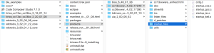
Before we can build the file we have a little housekeeping and settings to configure. We need to copy some startup files into our project from the CC1350 drivers folder.
On Mac OSX these are by default located at the following path:
/Applications/ti/tirtos_cc13xx_cc26xx_2_20_01_08/products/cc13xxware_2_04_02_17240/startup_files/ccfg.c
and
/Applications/ti/tirtos_cc13xx_cc26xx_2_20_01_08/products/cc13xxware_2_04_02_17240/startup_files/startup_ccs.c
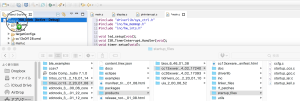
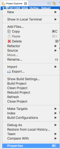
Drag and drop these into our project as shown in the image below.
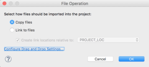
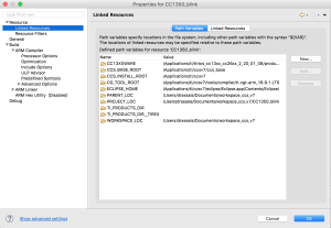
Next we need to open up the project properties and make some additions and changes to the project settings. Since we created an empty project some compiler and linker settings are not present that need to be.
We are presented with the following dialog.
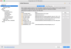
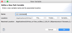
We are going to add a new entry, click New… and enter the following information. This is a variable pointing to the CC1350 driver library required for building.
Name:CC13XXWARE
Location:/Applications/ti/tirtos_cc13xx_cc26xx_2_20_01_08/products/cc13xxware_2_04_02_17240
This should now show up in the list as in the below image.
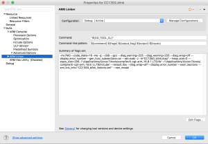
Next click on the ARM Compiler and click on Edit Flags.
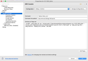
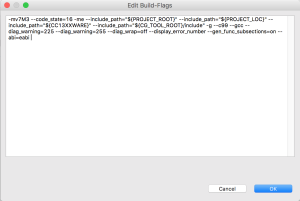
Replace the contents with the following test that includes the path for the CC13XXWARE drivers and click OK.
-mv7M3 --code_state=16 -me --include_path="${PROJECT_ROOT}" --include_path="${PROJECT_LOC}" --include_path="${CC13XXWARE}" --include_path="${CG_TOOL_ROOT}/include" -g --c99 --gcc --diag_warning=225 --diag_warning=255 --diag_wrap=off --display_error_number --gen_func_subsections=on --abi=eabi
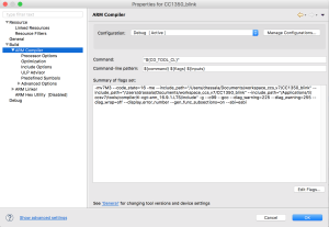
You should now have a screen that looks like this.
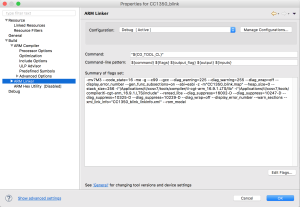
Next click on the ARM Linker and update the linker flags in there and press OK.
-m"${ProjName}.map" --heap_size=0 --stack_size=256 -i"${CG_TOOL_ROOT}/lib" -i"${CG_TOOL_ROOT}/include" --reread_libs --diag_suppress=16002-D --diag_suppress=10247-D --diag_suppress=10325-D --diag_suppress=10229-D --diag_wrap=off --display_error_number --warn_sections --xml_link_info="${ProjName}_linkInfo.xml" --rom_model
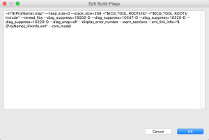
The ARM Linker screen should now look like this.
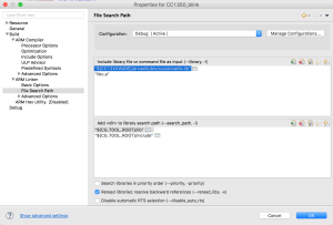
Finally we need to add a search path to the linker so it can find the CC13XXWARE drivers. Open up the ARM Linker and add the include path as shown below.
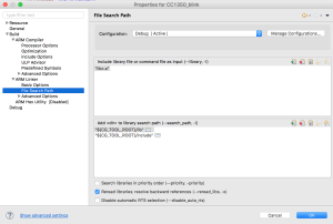
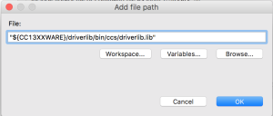
Under Include library file or command file as input click the + button and add the following text.
“${CC13XXWARE}/driverlib/bin/ccs/driverlib.lib”
Click on the up arrow to bring it to the top of the list, then press OK to save and close project settings dialog.
Now, build the project by right clicking it and choosing Clean Project (just to be sure everything is clean), then choose Build Project.
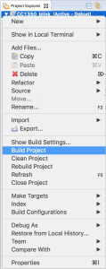
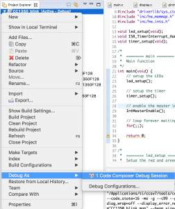
Next, ensure your CC1350 is plugged into your USB port, and choose Debug As.
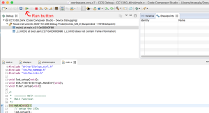
Finally, press the play button to run the code.
If everything goes correctly you should see a red LED and green LED flashing on the CC1350 LaunchPad as seen in the image at the top of the page.
This answers the questions about how to make a simple lightweight program for the CC1350, next is to add the logic to copy data from SRAM to FLASH and run this program completely from SRAM.
Hi Allan!
Thanks for publishing this snippet. I found it really very helpful! I’m currently working on a small footprint (wireless) bootloader for our scientific data loggers. They will be used for measuring the “Global Warming” (worldwide) and totally sealed (with a lifetime battery (Lithium AA) for 10 years operation). We use the CC1310.
Best regards, Jo
Hello Allan,
Thanks for publishing this code,it’s really very helpful. In this code timer triggers for every 350ms, and it uses clock frequency 48MHZ,I want 1sec timer for that i need to change the clock frequency,how to change clock frequency?
Sorry the reply is… late.
For this, you might not want to edit the clock, but the variables related to the timer period…
Playing with the TimerPrescaleSet value is one way of doing this.
The snapshots are missing . Please update. I m interested in getting the blink program running on my new MCU 🙂
Shashi
Sorry this took a while to notice, went through all the spam comments just now.
The issue is the images have “http” on them and not “https” so you are viewing a secure “https” page with insecure “http” content… the images.
I added a plugin to fix this on the fly when pages load, however, clicking on the image for the larger image still appears to load in “http” non-secure mode.