
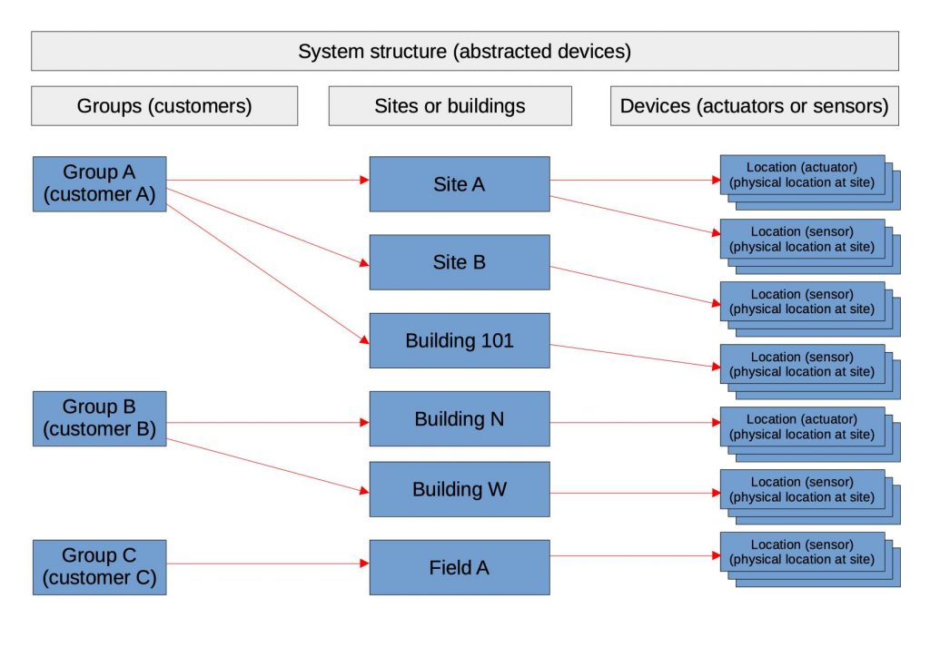
In the previous posts we talked about how to assign ids and organize the data, but ultimately we will need to store this information somewhere and a relational database (such as mySQL) would satisfy those needs. Below we have the following system structure for our data organized into groups (or customers) which each have one or more sites (or buildings) which then contain various sensors and actuators. These relationships can be seen below. The logical way to construct this data is to create a table for each type of data. We will then need to create the relationships and link the tables together.
Below we have constructed a number of tables to store the above data and some additional data useful for organization (not necessarily needed for system functionality). Each table will of course have a unique identifier (or id) and then from experience it is sometimes helpful to have a uuid (a globally unique identifier) in the case of data merging. This uuid has a very low chance of being duplicated and is useful if we need to merge data or backup/restore the database. The the autonumber id is automatically created as data is stored and it is sequential.
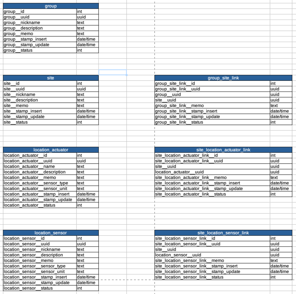
As far as the optional data we added a nickname, description, and memo. These three pieces of data are not required for system functionality but will help us name each data record with something we can relate to (and remember). We have also added some date/time stamps which will help us keep track of when the records are added/updated along with a status field so we may add status information such as active, inactive, etc. In the case of data deletion we could use the status to store a deleted “flag” as to mark the data as deleted but not actually delete it (since recovery of deleted data is not practical).
As for connecting the data we have created some “link” table that will allow us to create many-to-many relationships (or connections) between tables.
Concerning the use of “link” tables, depending on how the system will be used they may not be necessary, but, they have been added for flexibility. If we expect a site to be linked to one and only one customer then the link table will not be necessary and we can just add the “group__uuid” directly into the “site” table, however, with the addition of the link table (allowing many-to-many connections) a site could now be shared between more than one customer. Traditionally the id field is used to link tables but in this case we will link the data with the uuid. The uuid is a more nasty long number, but useful in the case of merging or backup/restore of the database.
At this point it is not known if this situation will arise, but if it does it will not be an easy task to go in and add the link tables at a later time, it will require quite significant changes to not only the database but also the code. Shifting around the data in the active database will also be required and it can be easy to make a mistake while copying/moving data records around.
We apply the same thinking to the location_actuator and location_sensor tables, allowing them to be shared between more than one site in the case one site overlaps with another. This will allow the flexibility to allow the sensors or actuators to be shared between multiple sites.
We are still dealing with the abstracted group-site-location data at this point, but in the end we will need to be able to link the actual hardware sensors to these virtual abstractions. In the next post we will look into the tables necessary for managing and sorting the actual hardware and the raw data.